 |
||||||||||||||||||||||||
|
BW202 Superheater Bypass Valve
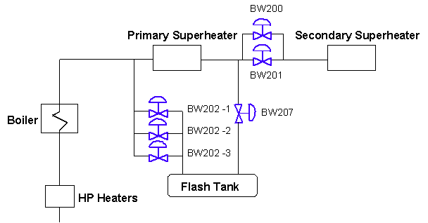
Application Discussion Operation of a Babcock and Wilcox (B&W) Universal Pressure (UP) once-through boiler requires that a minimum flow be established in the furnace waterwalls prior to firing of the boiler. This is to prevent overheating of the boiler tubes during initial operation. This requires the use of a bypass system that is integral with the main steam, condensate and feedwater systems so that the minimum flow can be maintained at startup and at times when the required minimum flow exceeds turbine demand. The bypass system also performs the following additional functions: • Reduces the pressure and temperature of the steam leaving the boiler during startup to conditions that are suitable for the flash tank, condenser and auxiliary equipment. • Provides a way of recovering heat from the feedwater that flows to the bypass system by utilizing the feedwater heaters. • Provides a means for conditioning the water during startup without delaying boiler and turbine warming operations. • Protects the secondary superheater against thermal shock from water during startup. • Provides a means for relieving excess pressure in the boiler during a load trip. With these functions in mind, B&W developed a bypass system that routes water from the main boiler feedpumps back to the flash tank during startup of the unit. Figure 1 shows a common startup configuration that includes the BW202 valve. This valve has a number of functions that are discussed below.
Figure 1: B&W UP Boiler Startup System During what is called the cold cleanup mode of operation, the BW202 valve is set to maintain 600 psig at the outlet of the primary superheater. The flow is bypassed from the primary superheater inlet to the flash tank. This occurs until the water chemistry is brought to a predetermined level when firing of the boiler begins. After firing of the boiler is initiated, the BW202 valve controls the primary superheater outlet pressure to 600 psig. Once the inlet temperature to the primary superheater exceeds 300F, the primary superheater outlet pressure is ramped from 600 psig to 3650 psig. This operation continues until the unit load reaches 20 – 25 percent capacity. At this point, the BW202 valve begins to close with the opening set point established at 4250 psig. If the boiler pressure reaches 4250 psig, the BW202 valve will open to act as a relief valve to prevent the safety valves from lifting. As can be seen by the above startup sequence, the BW202 sees a variety of service conditions. The first of which can be found in the cold cleanup mode, cold water passes through the valve. Since the valve is required to maintain 600 psig at the outlet of the primary superheater, the majority of the pressure drop must be taken across the valve. During this time, the flash tank is under minimal pressure making cavitation inevitable. Once firing is initiated in the boiler, pressure builds in the flash tank as the temperature of the inlet water increases. During this time, the pressure in the flash tank is below the vapor pressure of the incoming water. As the hot water flows through the valve, some of the fluid begins to flash, or turn to steam. As unit load approaches 25 percent, the valve is required to pass superheated steam and closes once unit load reaches 25 percent. The valve then remains closed until the event of a unit trip, when the valve is required to open and pass the entire unit load to the flash tank. In this application, the main mechanism for damage is the cavitation phenomenon. Cavitation is the formation and subsequent collapse of vapor bubbles in liquid flow streams and is a major source of damage in control valves and adjacent piping. Elimination of cavitation is accomplished through a staged pressure drop design that ensures the pressure of the fluid never drops below the vapor pressure. The staged pressure drop design also helps eliminate any damage that can be caused as the fluid begins to flash. Flashing damage is due to high velocity steam (formed when the pressure of the incoming fluid falls below the vapor pressure) carrying water droplets past metal components, which leads to smooth high velocity erosion. By staging the pressure drop, the amount of energy available is dramatically reduced by reducing the velocity, thus eliminating any damage to the trim components. As the process changes from water to steam, noise becomes a concern. Similar to controlling the cavitation and flashing issues, the staged pressure drop reduces the velocity of the steam thus limiting the amount of noise produced. To account for each of these phenomena, Fisher recommends the use of the Cavitrol anti-cavitation trim. This design eliminates damaging cavitation as the unit is first brought online. The staged design limits the amount of available energy at the trim exit reducing the effects of flashing and noise. It is also recommended to install this trim into an angle valve made of a chrome-moly alloy (WC9) material to resist any erosion damage to the valve body. While an angle valve is recommended, globe, offset globe and y-pattern constructions are available and have been used in many applications. |
|
|||||||||||||||||||||||

